上海睿米仪器仪表有限公司
地 址:上海.浦东.航头镇.乐城路30弄4号(201317)
电 话:021-58220307
传 真:021-68539811
邮 箱:contact@realmeter.cn
联系人:13601764364(谢先生)
网 址:www.realmeter.cn

Bilingual HTML (default: 中文) • v1.3 • 2025-12-28
Chapter 1–6 + Appendix A|统一修正版:复合流(分子/粘滞/壅塞/湍流)+ 几何等效路径|面向零基础读者(小白友好)
v1.3 修正要点:系统化“复合流 + 几何等效路径 + 大流量壅塞/湍流也可标准”的工程事实。
面向第一次接触真空与气体工程的读者
标准漏孔不是“坏掉的泄漏”,而是“被设计成稳定输出的小流量/大流量参考源”。
它的用途不是控制工艺气体,而是校准/验证:设备读数是否可信、是否一致、是否漂移。
标准漏孔并不要求单一分子流。它可以处于分子流、粘滞流、壅塞流,甚至伴随湍流。
“标准性”来自稳定机制(几何/压降/临界流)与可标定可复现,而不是流态标签。
要做采购/评审:读 Chapter 1–6,重点看 Chapter 5(工程对比)与 Appendix A(全流态工程参考)。
你是工程师要“抠机制”:直接读 Appendix A,里面给出统一判据与不确定度结构。
| 词 | 一句话解释 |
|---|---|
| 真空 | 压力比大气低得多的状态;压力越低,越接近“高真空/超高真空”。 |
| 标准漏孔 | 被设计成“稳定输出参考流量”的器件,用于校准/验证/健康检查。 |
| 分子流 | 高真空里分子彼此很少碰撞,主要撞壁面;此时“几何 + 温度”更主导。 |
| 粘滞流 | 分子彼此碰撞为主的流动;压降分布与黏度影响更明显。 |
| 壅塞流 | 在一定压比下局部达到声速,质量流量对下游压力不敏感,常用于大流量稳定输出。 |
| RGA | 残余气体分析仪:真空里的质谱仪,按质量数读峰。 |
| mbar·L/s | 常用的吞吐量/泄漏率单位,可理解为“每秒进入系统的气体量”。 |
| MFC | 质量流量控制器:用于过程供气的主动控制器(擅长控制,不擅长当基准)。 |
| 可溯源 | 结果可追溯到校准链路与参考标准(有证据、有路径)。 |
目标:让你理解“为什么一个被设计的泄漏,可以变成工程基准”。
工业里提到“泄漏(Leak)”往往意味着缺陷。但在计量与真空工程里,有一种“泄漏”是被故意制造出来的:它的几何结构、材料、气体、温度条件都是可控的,因此它输出的是稳定、可重复的参考流量。
在不同流量区间,流动可能呈现分子流、粘滞流、壅塞流甚至湍流。但只要存在一个主导的、被动的约束机制把时间平均质量流量锁定(例如几何约束、压降分布约束或临界质量流约束),它就可以成为工程基准。
早期:用来判断“有没有漏”。
中期:用来验证检漏仪是否还能工作(稳定性开始重要)。
现在:在 RGA、流量计、检漏系统里,标准漏孔成为“参考注入源”,用于校准/一致性验证/健康检查。
REALMETER® 标准漏孔的定位:工程参考基准(Engineering Reference)。
目标:让你明白“你到底在相信什么”,以及为什么它可复现。
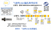
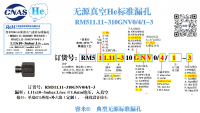
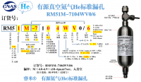
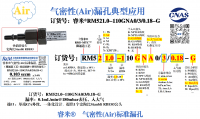
REALMETER®(睿米)标准漏孔的核心结构是几何高度可控的微通道。从物理意义上讲,它就是工程化的理想圆管毛细管(Micro-capillary):孔径、长度、入口/出口边界、气体与温度条件都可定义,从而实现可建模、可标定、可规模复现。
“被动”不是落后,而是把稳定性建立在物理约束上:无传感器、无控制回路、无主动调节。标准漏孔的目标不是“设定并控制某个流量”,而是在给定工况下输出一个不会自己动的参考点。
REALMETER® 标准漏孔覆盖范围可从 1×10⁻¹² mbar·L/s 到 100 mL/s(甚至更大)。在这一跨度里,微通道内可能出现分子流、粘滞流、壅塞流,甚至在高流量下伴随湍流。这不否定标准性——标准性来自稳定机制(几何/压降/临界流)与可标定、可复现。
在指定目标漏率或质量流量下,可以通过不同(d, L)组合实现同一工程输出。因此,“流量相同 ≠ 内部流动状态相同”;分子/粘滞/壅塞/湍流的比例是设计结果,而不是“是否标准”的前提。
| 流量/漏率区间 | 常见流动特征 | 稳定性主要来源 |
|---|---|---|
| 极低漏率(~10⁻¹² mbar·L/s) | 分子流为主 | 几何 + 温度 |
| 中低漏率(~10⁻⁸ ~ 10⁻⁶ mbar·L/s) | 分子/粘滞复合(比例连续变化) | 可建模/可标定的连续区约束 |
| 较大漏率(~10⁻³ mbar·L/s) | 粘滞流为主 | 压降分布 + 几何 |
| 大流量(10–100 mL/s 甚至更高) | 壅塞流 / 可能伴随湍流 | 临界质量流锁定 + 几何 |
目标:把“能用/不能用”说清楚,避免误用带来工程灾难。
稳定的边界条件:上游供气状态、温度条件在使用周期内可控/可监测。
可标定与可复现:输出可通过证书或校准链路被量化。
避免强反应/强吸附导致几何或表面状态缓慢变化:否则基准会漂移。
你需要动态调节流量(那是 MFC 的工作)
你需要“快速闭环控制”而不是“参考注入/验证”
强反应/强吸附气体导致通道性质变化不可管理
你想把它当“唯一绝对流量计”而不做误差预算
当 MFC 用:试图“设定一个流量”。标准漏孔提供的是“参考流量”。
当缺陷件用:把它理解成随机泄漏。标准漏孔恰恰相反,是“被设计得可重复”。
忽略边界条件:不监测温度与供气状态,却要求绝对不变。
目标:用 Fab / 设备厂工程师的语言说明:它在系统里到底解决什么问题。
质量轴锚定:用已知气体峰确认质量轴没有跑偏
灵敏度一致性验证:同样注入,响应是否一致(跨时间/跨腔体)
健康检查:漂移趋势是否异常(提前发现问题)
产线最怕的不是“指标严”,而是读数不稳导致误判。标准漏孔更像一个“系统自检件”,帮助区分:是产品漏,还是设备/状态变化。
班前/班后自检
多台设备横向一致性对比
接近判定阈值时的溯源辅助
重分子碎片谱复杂、系统记忆效应强,很多时候你真正需要的是一个长期稳定的参考注入,用于做趋势对比与仪器健康判断。
目标:把“为什么不能用别的东西替代标准漏孔”一次性说透(v1.3 统一口径:稳定机制视角)。
标准漏孔可跨越分子流、粘滞流、壅塞流甚至伴随湍流。只要时间平均质量流量被主导物理约束“钉死”(几何/压降/临界流),就可以稳定、可复现、可标定。
“毛细管不好当基准”这句话只对未工程化的毛细管成立:几何不可控、表面状态不可控、入口边界不可控,导致长期可比性差。
低流量接近噪声底:零点漂移与噪声成为主要误差
闭环引入新的失效模式:滞后、振荡、参数漂移
个体差异与老化:跨设备一致性难保证
工程总结:MFC 适合“执行与调节”,标准漏孔适合“提供固定参考点”。
孔板计量常依赖压差模型。对跨越多个数量级的真空/低流量场景,模型适用性与边界条件敏感性会变得难以统一管理,因此更适合特定工况的工业测量,而不是全区间工程基准。
在 10–100 mL/s 甚至更高流量段,微通道可能进入壅塞流并伴随湍流。壅塞条件下质量流量对下游扰动不敏感,主导机制是临界质量流锁定 + 几何固定,因此时间平均流量仍可高度稳定,常用于 MFC/流量计校准。
| 器件 | 主要目的 | 稳定性来源 | 做工程基准的适配性 |
|---|---|---|---|
| 普通毛细管 | 简单限流 | 偶然几何 + 不可控边界 | ❌ |
| REALMETER® 微通道标准漏孔 | 参考注入/校准/验证 | 几何/压降/临界流(被动约束) | ✅ |
| MFC | 过程控制 | 闭环控制 | ⚠️(不适合作为基准) |
| 孔板 Orifice | 特定工况测量 | 压差模型 | ⚠️(跨区间受限) |
目标:用工程中立语言说明“产品体系在计量坐标系里的位置”。
工程上更关心:你在校准/验证什么?是单点锚定,还是系统一致性?是轻质气体,还是重分子?
用于单质量点/单通道锚定
用于检漏系统灵敏度验证
作为更复杂校准体系的底座
一次注入覆盖多个质量点
验证质量轴线性与相对灵敏度一致性
更适合“对比/健康检查”,而非追求单点绝对值
为材料放气/AMC 提供长期可比的参考注入
帮助区分“材料变化”与“仪器变化”
它们的核心意义不是“控制流量”,而是控制“是否接入基准源”,并尽量减少死体积/背景变化,让基准使用更工程化、更可流程化(PM)。
本附录给工程评审/技术尽调使用(v1.3:全流态 + 统一判据)。
REALMETER® 微通道标准漏孔在物理意义上就是毛细管,但属于几何、边界与材料状态被工程化定义、并可规模复现的理想圆管微通道体系。
在大量典型漏率区间(例如 10⁻⁸~10⁻³ mbar·L/s),分子流与粘滞流往往同时存在,比例随压力、流量与几何连续变化。工程关键是:该连续区内关系可建模、可标定、可复现。
在 10–100 mL/s 甚至更高流量段,微通道可能进入壅塞流并伴随湍流。壅塞条件下质量流量对下游压力扰动不敏感,主导机制是临界质量流锁定与几何固定,因此时间平均流量仍可高度稳定,可用于流量计/MFC 校准。
在同一目标漏率/流量下,可通过不同(d, L)组合实现同一工程输出。细短与粗长路径将导致不同的流态比例与敏感性,但都可以形成稳定基准。流态比例是设计结果,而不是资格证。
| 不确定度来源 | 影响强度 | 能否监测 | 工程处理方式 |
|---|---|---|---|
| 温度变化 | 常见一阶主导 | 是 | 监测/恒温/修正 |
| 几何偏差(d, L, 入口边界) | 制造一阶 | 间接 | 批次一致性与统计控制 |
| 气体物性差异 | 固有 | 是 | 单气体基准;混气做系统一致性 |
| 表面状态变化 | 二阶 | 部分 | 老化管理与趋势监测 |
| 上游供气状态 | 可显著 | 是 | 稳压/稳流/监测 |
Full English mirror of Chapter 1–6 + Appendix A (no omissions; English may be longer for clarity)
In most industrial engineering contexts, the term “leak” is commonly associated with defects, failures, or inadequate risk control. However, in metrology and vacuum engineering, there exists a class of leaks that are intentionally engineered. Their geometric structure, material state, working gas, and temperature conditions are all controlled and well defined, allowing them to deliver a gas flow that is long-term stable, repeatable, and calibratable.
Such engineered leaks are not system abnormalities, but rather passive reference sources. Their engineering purpose is not to allow uncontrolled gas ingress into a system, but to provide, under specified conditions, a known, stable, and repeatable gas injection into the system under test, so that the response of the instrument and the system itself can be evaluated.
For readers encountering this concept for the first time, a standard leak source can be intuitively understood as a “standard titration device” or a “reference stimulus source” within a vacuum system. Its role is not to participate in process control, but to apply a known input signal to the system, thereby allowing verification of whether the measurement results are trustworthy.
In many simplified technical descriptions, standard leak sources are often assumed to require operation in the molecular-flow regime in order to remain stable. This understanding is incomplete from an engineering perspective. In reality, depending on the leak-rate or flow-rate range, gas transport inside a standard leak may exhibit molecular flow, viscous flow, molecular–viscous transitional flow, and, under high-flow conditions, may even enter choked-flow regimes or be accompanied by turbulent components.
Whether a standard leak source is valid does not depend on which flow regime it “appears” to operate in, but rather on whether, under the specified operating conditions, there exists a dominant passive physical governing mechanism that locks the time-averaged mass flow rate into a stable, repeatable, and calibratable output.
Such dominant governing mechanisms may manifest as geometric constraints, distributed pressure-drop constraints, or, under specific conditions, mass-flow locking associated with choked flow. As long as this mechanism remains stable during operation, a standard leak source can function as an engineering reference across an extremely wide flow range.
Therefore, a “standard leak source” is not a special device restricted to a particular flow regime, but rather a class of engineering reference sources that achieve stable output through passive physical constraints. Understanding this point is a prerequisite for correctly interpreting the physical principles, engineering design choices, and application boundaries discussed in the subsequent chapters.
The core physical structure of a REALMETER® standard leak source is a geometrically well-defined micro-channel. From a physical standpoint, it is an engineered ideal round-tube capillary (micro-capillary), whose diameter, length, inlet/outlet boundary conditions, working gas, and temperature conditions are all definable and reproducible.
In an engineering context, “passive” does not imply simplicity or obsolescence. Rather, it indicates that the device does not rely on sensors, feedback control loops, or active regulation during operation. A standard leak source does not attempt to “control” flow; instead, under specified conditions, it provides a reference output that does not drift by itself.
In a REALMETER® micro-capillary standard leak source, the output flow is jointly determined by several factors: the geometry of the micro-channel (diameter and length), the physical properties of the working gas, and the operating temperature. In practical engineering use, one prerequisite must also be satisfied: the upstream gas supply state remains stable over the period of use.
In many introductory descriptions, standard leak sources are often simplified as “molecular-flow devices.” While such descriptions may be pedagogically convenient, they are incomplete from an engineering standpoint. In reality, REALMETER® standard leak sources can cover an extremely wide range from ultra-low leak rates to very high flow rates, and the internal flow regimes vary continuously with operating conditions.
Under a specified target leak rate or mass-flow condition, the same engineering output can be achieved through different combinations of micro-channel geometry. This means that, in standard leak design, there is no single “correct” geometric solution.
For example, at the same target flow rate, one may employ a micro-channel with a smaller diameter and shorter length, or alternatively a channel with a larger diameter and longer length. These two approaches are engineering-equivalent in terms of output, but their internal flow behaviors are not identical.
In a “thin and short” geometric path, local flow velocity is typically higher and the Reynolds number is correspondingly larger. As a result, viscous flow tends to dominate at moderate to high flow rates, and choked flow or even turbulent components may occur. In contrast, in a “wide and long” path, pressure drop is distributed along the channel length, wall interactions become more significant, and the proportion of molecular flow or molecular–viscous mixed flow may be higher.
It must be emphasized that the differing proportions of flow regimes described above do not negate the validity of the device as a standard leak source. Flow-regime ratios are outcomes of geometric choices and operating conditions, rather than eligibility criteria for being considered “standard.”
In the ultra-low leak-rate range, stability is typically governed by geometric constraints and molecular thermal motion. In intermediate leak-rate ranges, stability arises from continuous-flow pressure-drop relationships that can be modeled and calibrated. In high-flow ranges, stability may originate from mass-flow locking under choked-flow conditions.
Therefore, a REALMETER® standard leak source is not a device constrained to a particular flow regime, but an engineering reference system that leverages geometric design freedom to achieve stable output across different flow ranges.
It must be made explicit that a standard leak source is an engineering reference device, not a universal flow device intended for process gas delivery or flow regulation. Its engineering value lies in providing a stable and repeatable reference injection, rather than fulfilling requirements for dynamic adjustment or closed-loop control.
In practical applications, for a standard leak source to function as an engineering reference, several preconditions must be satisfied. These conditions are not optional add-ons; rather, they form the foundation upon which stability and calibratability are established.
First, the operating boundary conditions of a standard leak source must remain stable, particularly the upstream gas supply pressure, temperature, and the surrounding thermal environment. If these conditions vary significantly, the output flow rate will change accordingly, even if the geometric structure itself remains unchanged.
Second, the output of a standard leak source must be calibratable and reproducible. This means that under identical operating conditions, the leak source should exhibit consistent engineering behavior across different times, different production batches, or different individual units.
For certain gases or application scenarios, long-term changes in the surface state of the micro-channel must also be considered. Phenomena such as adsorption, chemical reactions, or contamination may cause the effective geometry or flow characteristics to drift slowly over time, thereby impacting the reliability of the device as an engineering reference.
In the following application scenarios, standard leak sources are not appropriate solutions, and forcing their use may instead introduce additional uncertainty or engineering risk.
If the application objective is to dynamically adjust flow rates according to a setpoint or to respond rapidly to changing operating conditions, active control devices such as mass flow controllers (MFCs) should be used instead of standard leak sources.
For gases that are strongly reactive or strongly adsorptive, the physical and chemical state inside the micro-channel may undergo uncontrolled changes over time, thereby undermining the long-term stability of the standard leak source.
The engineering role of a standard leak source is that of a reference source, not a standalone absolute flowmeter. Using it directly as an absolute measurement device without proper error budgeting and uncertainty analysis is inappropriate.
In practical engineering applications, the following three types of misuse are most common and are also the most likely to lead to misinterpretation of the capabilities of standard leak sources.
A standard leak source cannot actively adjust its output according to a setpoint; its stability arises from passive physical constraints rather than from a control loop. Treating it as a mass flow controller is therefore a conceptual error.
If a standard leak source is regarded as an uncontrolled or random leak defect, its engineered design and calibration basis are overlooked, leading to incorrect doubts about its stability and credibility.
Demanding “absolute invariance” from a standard leak source while failing to monitor or control key boundary conditions such as temperature and gas supply state is unrealistic from an engineering standpoint.
Correctly understanding the engineering applicability boundaries of standard leak sources helps prevent misuse and ensures that their value in calibration, verification, and system health monitoring can be fully realized.
In semiconductor manufacturing and related high-end production environments, many critical inspection and monitoring steps are not primarily concerned with whether a leak exists, but rather with whether the measurement system itself is operating in a trustworthy state. Standard leak sources are introduced into Fab environments precisely within this context.
In semiconductor and lithography equipment, residual gas analyzers (RGAs) are widely used to monitor gas composition inside vacuum chambers. Standard leak sources can be used to inject gases of known species and known throughput into the system, thereby enabling mass-axis anchoring and sensitivity consistency verification.
By periodically introducing the output of a standard leak source under fixed conditions, it becomes possible to assess whether the response of an RGA or related detection system changes over time. Such applications do not rely on absolute flow accuracy, but rather on relative response consistency.
In helium mass-spectrometer leak-testing systems used in the new energy industry, standard leak sources are commonly employed for system self-checks and sensitivity verification, rather than for direct product acceptance decisions. Their role is to distinguish between issues associated with the test object and issues related to the instrument’s own condition.
In material outgassing tests, standard leak sources can serve as stable reference injection sources to verify the response stability of the test system over long-duration measurements, thereby improving the comparability of results across different batches or different experiments.
For AMC or high-molecular-weight outgassing monitoring scenarios, standard leak sources can provide stable reference signals in the high-mass range, supplementing detection regions that are difficult to cover using conventional light gases.
From a Fab engineering perspective, a standard leak source is not a component of any specific process step, but rather a cross-tool and cross-process engineering reference instrument. Its value lies in providing a repeatable and traceable “baseline stimulus” for complex systems.
When used appropriately across different industrial scenarios, standard leak sources can significantly enhance the consistency and credibility of measurement systems. However, this value is always contingent upon respecting their engineering role and applicability boundaries.
This chapter does not compare which device is “more advanced,” but explains why certain commonly used devices are not suitable as engineering reference standards.
The objective of an MFC is active regulation to a setpoint; its core capability is dynamic control, not serving as a passive long-term reference.
An MFC relies on sensors and a control loop. Sensor drift, zero offset, algorithm behavior, and unit-to-unit variation can be acceptable in control tasks, but introduce additional uncertainty when used as a reference.
An MFC is an excellent controller, but not suitable as a passive, long-term stable reference source.
A REALMETER® standard leak is physically a capillary. The key difference is whether the capillary is engineered with controlled geometry, boundary conditions, and managed surface state.
Ordinary capillaries often lack strict control of diameter, length, inlet/outlet boundaries, and surface state; performance becomes dependent on individual variation and usage history, which undermines reproducibility as a reference.
It is not that “capillaries cannot be standard leaks”; rather, non-engineered capillaries are unsuitable as engineering references.
Orifices typically infer flow from upstream/downstream pressure differentials; models are mature in continuous-flow and higher-pressure regimes.
Across multiple orders of magnitude in vacuum, model validity degrades and sensitivity to boundary changes increases, limiting reliability as a universal reference.
Orifices can be effective flow elements in specific ranges, but are not ideal as long-term, cross-regime standard reference sources.
Standard leak stability does not depend on active control or a single-regime assumption, but on passive governing constraints such as geometry, distributed pressure drop, or choked-flow locking.
A standard leak is not a universal replacement for MFCs/capillaries/orifices; it is an irreplaceable tool specifically for the engineering standard/reference role.
This chapter explains functional positioning of standard leak types within measurement/calibration/verification frameworks, rather than product marketing.
In engineering practice, classification should be based on functional roles, not on product model numbers or external form factors.
Single-gas standards provide clear, interpretable reference injections and are suitable for mass-axis anchoring, sensitivity verification, and single-variable stability checks.
They are not meant to simulate complex process atmospheres; their value is low-complexity, high-controllability references.
Mixed-gas standards cover multiple mass ranges in one injection, supporting multi-channel consistency verification and system-level response assessment.
Their purpose is system consistency checks rather than high-precision quantification of each component.
High-mass standards cover regions not easily covered by light gases and are valuable for material outgassing and AMC monitoring.
They do not attempt to reproduce complex chemistry; they provide repeatable reference signals.
Valve control enables engineering control over when injection occurs without changing the reference nature of the leak source.
Valve/integration improves system integration and convenience; it does not change the engineering positioning of a standard leak source.
An engineering-neutral mapping clarifies roles and helps avoid misselection or misuse.
This appendix provides systematic engineering guidance on major physical models, uncertainty sources, and applicability boundaries, rather than claiming a single universal closed-form solution.
Under extremely low pressure and ultra-low leak-rate conditions, intermolecular collisions can be neglected and molecule–wall interactions dominate; molecular-flow models may be used.
Molecular-flow model applicability is constrained by operating conditions; as pressure, flow, or scale changes, the assumptions gradually become invalid.
Many standard leaks operate in the molecular–viscous mixed/transitional region, where single-regime models are often insufficient.
At high flows, choked flow may occur, sometimes with local turbulent components. This does not negate standard-leak validity; the key is that the time-averaged mass flow can still be locked by stable governing mechanisms.
Standard leaks focus on statistical time-averaged mass flow rather than instantaneous micro-states. If the average remains stable under specified conditions, it can serve as an engineering reference.
Uncertainty in engineering use primarily comes from:
A.7.1 Temperature-related uncertainty: affects molecular thermal motion and gas properties, directly impacting output.
A.7.2 Geometric manufacturing tolerances: diameter/length/shape tolerances; managed via design & production control.
A.7.3 Variations in gas properties: differences across gases/mixtures must be explicitly considered in modeling and calibration.
A.7.4 Surface state and aging effects: adsorption/contamination/slow reactions may introduce long-term drift.
A.7.5 Upstream supply conditions: pressure/stability directly affect output and must be monitored/controlled.
This appendix summarized key models, boundaries, and uncertainty sources, forming an engineering basis for appropriate use.